In circuit-1 and circuit-2 shown in the figures, R 1 = 1Ω, R 2 = 2Ω and R 3 = 3Ω. P 1 and…
Physics · JEE Advanced · NTA Exams — Current Electricity
In circuit-1 and circuit-2 shown in the figures, R1 = 1Ω, R2 = 2Ω and R3 = 3Ω.
P1 and P2 are the power dissipations in circuit-1 and circuit-2 when the switches S1 and S2 are in open conditions, respectively.
Q1 and Q2 are the power dissipations in circuit-1 and circuit-2 when the switches S1 and S2 are in closed conditions, respectively.
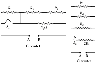
Which of the following statement(s) is(are) correct?
P1 and P2 are the power dissipations in circuit-1 and circuit-2 when the switches S1 and S2 are in open conditions, respectively.
Q1 and Q2 are the power dissipations in circuit-1 and circuit-2 when the switches S1 and S2 are in closed conditions, respectively.
Which of the following statement(s) is(are) correct?
- When a voltage source of 6 V is connected across A and B in both circuits, P1 < P2 .
- When a constant current source of 2 amp is connected across A and B in both circuits, P1 > P2.
- When a voltage source of 6 V is connected across A and B in Circuit-1, Q1 > P1 .
- When a constant current source of 2 amp is connected across A and B in both circuits, Q2 < Q1.
Answer
(D) When a constant current source of 2 amp is connected across A and B in both circuits, Q 2 Q 1 .
Sign up free on Edukali to view the step-by-step worked solution and practice thousands of similar questions.
Related practice questions
- A Galvanometer is an instrument that can be used to construct an ammeter for measuring current .It can be…
- In the given circuit, with steady current, the potential drop across the capacitor must be
- In a circuit shown in the figure, the capacitor C is initially uncharged and the key K is open. In this…
- A physical quantity is defined as S = E imes B _ 0 , where, is electric field, is magnetic field and m 0 is…
- A Galvanometer is an instrument that can be used to construct an ammeter for measuring current .It can be…
- The potential difference applied to an X-ray tube is 5kV and the current through it is 3.2 mA. Then the…
- Figure shows three resistor configurations R 1 and R 2 and R 3 connected to 3 V battery. If the power…
- In the circuit shown the resistances are given in ohms and the battery is assumed to be ideal with e.m.f…
More Current Electricity questions · Browse all practice questions